Major Achievements:
- Developed a fully-fledged testing platform for air-breathing RDEs at UCF
- Laid the foundation for a future senior design teams
- Produced data for several AIAA SciTech 2025 papers
Background
Rotating Detonation Engines (RDEs) are a relatively novel form of rocket propulsion that takes advantage of pressure-gain combustion. Conventional rocket engines use constant-pressure combustion cycles. RDEs theoretically produce better performance by taking better advantage of the energy stored chemically in the propellants. There is a fine line between detonating in the way that yields the performance advantage, and detonating in the way that destroys the engine. Due to the speeds involved in the process, these engines have only recently began gaining traction now that computers and sensors allow for the extremely fast sampling rates necessary for reliable data output. Their compact size and efficiency gains allow for storable propellants to be used more effectively in missile and defense applications.
The goals of this project at the beginning were beyond creating a working air breathing lab scale engine, to lay the foundation for further research to be done at UCF. This involved creating a test stand equipped with a capable and robust data acquisition system and control system. Considering the tight budget for a project of this ambition, it took a lot of creativity and clever thinking to get it off the ground (metaphorically).
Design
Ignition
Lighting an RDE involves precise timing and a strong enough relese of energy to induce a detonation mode within the engine. A fast burst (in tens of micro seconds) with not a lot of energy is more likely to induce a detonation compared to a longer burst with a ton more energy. Typically predets (short for predetonator tube) are used where an explosive mixture of gases are lit on one end of a long tube. Over this length of tube, the energy release is structured in such a way a shock is developed by the time the combusting gases exit. Due to the mechanism of operation, these have careful geometry that is hard to package into a system with compact and flight in mind. This is where my approach comes in, conventional torch. If the annulus can act as the constriction that focuses the energy towards a shock, the igniter can be more compact and allow for smaller designs for flight vehicles. After all, the annulus needs to already be able to contain and direct the energy to keep the detonation wave circling around the cavity.
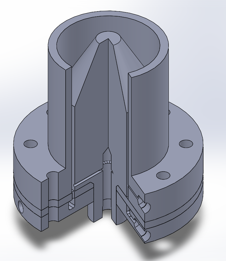
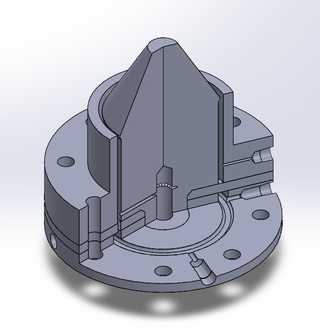
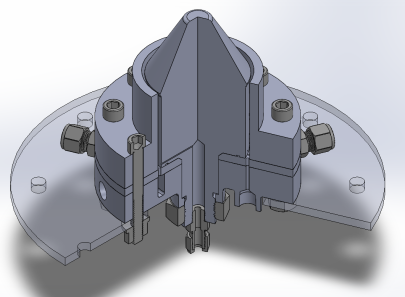
I was in charge of both mechanical and electrical aspects of the ignition system. In terms of the mechanical side of things, I prioritized cost and ease of manufacturing over anything else, arriving at what is essentially a modified stainless steel 1/4 NPT cross fitting, as pictured below. The torch body is then connected to the rest of the RDE via a thick-walled stainless steel pipe nipple. I truly didn’t want the torch to be plagued by scope creep, so it incorporates as much stuff off the shelf as I could find.
With this in mind, the electrical system employs a standard car ignition coil, the cheapest I could find on Amazon. The circuit puts a 12V SPDT relay in purgatory by switching it rapidly between powering its own coil and pulsing the primary of the ignition coil. The best analog I could come up with was those “useless machine” desk toys where turning on the switch powers on the arm to turn itself off. The relay coil is wired to 12V via its Normally Closed contact in series with a momentary switch. When the switch is closed, the contact opens, powers it down, which allows it to return to rest and keep cycling.
Additionally, I added a couple capacitors and resistors finetune exactly how long the charging and discharging takes in order to ensure the primary winding of the ignition coil has time to fully saturate before the power is switched off and the fields collapse to generate the high voltage out of the secondary. I could’ve gone with something based on a 555 timer or even more fancy, but circling back to that thought about scope creep, I truly just wanted it to work and work without needing to think about it. The only drawback is that mechanical relays really don’t like being switched that fast, and because the coil within the relay is also an inductor, there’s plenty of arcing when it’s disconnected during the cycling. Adding a flyback diode across reduced the switching frequency so I arrived at the conclusion that relays are cheap enough to be consumable. During testing, the poor little relay did not fail or weld itself shut once, but if I were to be pulled back to the drawing board for a proper vehicle-born ignition system, I’d probably choose to go with something solid state or capacitor-based much like modern cars use for their sparking.
A cheeky extra feature I added to the torch is the presence of a pressure transducer line. During startup, the transducer would report the torch internal pressure, but once it’s powered down, it’d act as a CTAP (Capillary Tube Attenuated Pressure) readout for the annulus conditions. The transducer is coupled to the chamber via a 1/4" stainless steel tube to thermally isolate it from the extreme conditions during both startup and steady state operation. The length of tubing necessary was determined via the following function:
\[ \begin{aligned} \frac{T-T_{\inf}}{T_{0}-T_{\inf}}=\frac{1}{\cosh(\sqrt{\frac{4hD_{1}}{12k(D_{1}^{2}-D_{2}^{2})L}})} \end{aligned} \]where:
- $T$ = Maximum tolerable temperature at point of interest
- $T_{\inf}$ = Temperature of environment, taken as 100F for this analysis
- $T_{0}$ = Temperature of pressure source of interest, in this case, the estimated combustion temperature
- $L$ = Length of tubing, in inches
- $h$ = Heat transfer rate from tube to still air by natural convection, in BTU/hr/ft^2/ºF
- $D_{1}$ = outside diameter, in inches
- $D_{2}$= inside diameter, in inches
This model assumes the thin walled tube to be a fin following conduction and convection, much like a heatsink fin. The fin is expected to lose heat by convection at its end, and the pressure source is assumed to only transfer heat via the tube wall and through the pressure media. Another major assumption is that due to the thermal conductivity coefficient difference between the pressurized gas and the metallic walls of the tube, that the heat transfer via the stagnant gas is negligible. This leaves us with a tube length of around 8 inches. I ended up rounding up to 12 just in case we found anything extreme during testing and because the transducer was borrowed and VEEERY expensive. Please bear with me and the demonic US customary heat transfer calculation. I just like inches :^)
In the end, and because our entire operation relied on this very experimental approach working first try, I designed around being able to swap the torch out for a predet and still be able to use all propellant and control connections as normal. By keeping it as a drop-in replacement, we could quickly fall back on something that’s known to work properly and carry on with testing the combustor. There are so many unknowns in RDEs due to the technology’s low TRL that being able to rule out variables saves plenty of long nights of testing at the lab.
As expected, the concept of lighting the RDE was a lot easier said than done. I go more into detail about the outcome under Testing, but the combination of a tight testing timeline, flawed assumptions in the annulus design, and the very experimental torch approach led to us switching it out to try and diagnose the combustor directly.
Structure
Before pivoting towards my work in ignition, I helped with the first handful of iterations of the combustor. I focused on packaging and routing alongside my buddy Hunter, essentially figuring out how to efficiently route propellants from their respective ports coming from the fluids system and into the injectors.
Initially, we weighed the our options for manufacturing methods. We could push for an additively manufactured design, which would allow for complex geometry and reduce the number of critical seals to worry about, but had the drawback of very money, timeline, and risk intensive. On the other hand, we could go for something doable with the resources available at the UCF Machine Shop: reliable and free access to 3 and 5 axis machining, turning, EDM hole drilling and wire cutting. All we’d have to source is our required material. Regardless of whether we printed it or machined it conventionally, the RDE would be exposed to extreme conditions surrounding the detonation wave as it propagates, which means high pressures and temperatures sweeping around in a circle. Compared to a conventional engine, the cyclic failure modes began rearing their ugly head in all of our analysis.
The only saving grace was that the timescales for all this energy release were minuscule, although they compounded over time. Based on the fact we were targetting a very short runtime of only a couple seconds (and much more engineering analysis I will not go into here), we decided to go for 304 Stainless Steel. The reasoning came down to the fact we wanted the ability to fail and iterate without being dead in the water trying to source another brick of material to machine or a whole new printed part. Much of the research behind RDEs is uncharted territory, so even with all of our calculations and analysis double, triple, and quadruple checked, we wanted a large margin of safety on top of the ability to return to the drawing board and modify our design without crippling the project. So with all that being said, we settled on a conventionally manufactured combustor. From all the discussion, preliminary analysis, and talking to researchers both at UCF labs and across the US in places like Purdue and Johns Hopkins, we went for a modular design based on a stack of plates. Below are some of the first iterations of our combustor, initially by me and later modified by Hunter.
A great start, but with any engineering project, we quickly started spotting flaws in terms of component integration, manufacturing, and especially in terms of final assembly in the stand. Looking back while writing this knowing how the project turned out as a whole makes the original design look extra alien. We moved away from fastening the inner body via a huge nut in the back, moved towards longitudinal fluid connections for both of the propellants, and most importantly, designed towards being able to fully assemble the combustor without needing the thrust plate. This last detail made it infinitely easier to mount and remove the combustor onto the test stand during testing. I truly don’t know what horrors we would’ve gone through if we needed the thrust plate involved while putting together everything else.
In the end, the combustor consisted of an inner and outer body, nozzle cowl and spike, and the injector plate and backing plate. The inner and outer body constrain the annulus dimensions and their negative space form the cavity where the combustion occurs. The inner body, however, also acts as part of the internal plenum for one of the propellants. The selected injector schema is “Jet-in-Crossflow”. As the name implies, one of the propellants is injected perpendicular to the other. In our case, the hydrogen flows radially out from the inner body as the air is injected longitudinally.
As for the nozzle spike and cowl, we decided on constricting the opening at the end of the annulus to raise the static pressure after the propellants are injected, as it has the effect of increasing detonability and aiding in ignition. It ensures propellants remain within the chamber for longer, which also helps the process overall.
The Rest Of It
I would love to keep writing much more about all that this project entailed, but it ultimately was a deeply intertwined group contribution. I am highlighting my direct work on getting this RDE off the ground, so it wouldn’t be fair to any of my teammates to mention it all without also highlighting their achievements. A major part of senior design at UCF are these “Milestone Reports” where we, as a team, got together and tracked our work in a format similar to a design review. Milestone 6, the final one, contains a snapshot of the past year of our work leading up to the results we got and how we’d improve upon our work if we were to hypothetically continue testing after the semester ended. I feel it’s the best way to provide a curious reader, perhaps someone looking to base their research on our work, with the necessary in-depth info about the combustor, test stand, and our results. Please reach out to me directly if you have any questions. Email is best, all available over on the sidebar.
Here it is, weighing in at 134 pages.
To go along with the report, I’d also like to provide a quick slidestack that we used to give an overview about the project. I can’t embed it as a .pptx, so unfortunately, gifs will not work on this version. Enjoy!
However, I’d like to still cover what we experienced taking the design from a whiteboard/Solidworks to a real, working prototype. I’ll also be covering my contribution to our combined in-the-field problem solving and troubleshooting. Just know it’ll all be in a very simplified manner because, after all, we wrote that document precisely to act as a self-contained reference guide to our system. I might revisit this section and put together a quick rundown of our test stand, fluid system and DAQ and control electronics.
Testing
The testing campaign began with stress testing our control and data acquisition system by running the torch igniter over and over again. If we could pick out the bugs in our VIs, wiring, and sensors before moving onto the big leagues of trying to run the combustor with all the timings involved, we’d save a lot of pain and suffering down the road.
The torch seemed promising on its own, however, no matter what we did it struggled to resist being blown out against the main propellant flow, so at this point we decided to pivot onto the predet and continue testing the combustor itself. Look at the predet in action:
We still weren’t getting any ignition at this point, so we returned to the drawing board. After combing through the footage and data gathered so far, we were led to the conclusion that two factors were in the way. A: the hydrogen jets coming out of the inner body struggled to penetrate the column of air being injected, contributing to terrible mixing and a suboptimal local equivalence ratio. Although the design total equivalence ratio was correct and it was confirmed by sensor data, the gases weren’t being mixed due to their extreme difference in velocities. At this point we decided to increase our injector pair count from 20 to 32, as this would decrease the relative mass flow of air per injector element and possibly alleviate these issues. Look below for one of the tests from the 2nd injector iteration.
The impact this relatively simple fix is what leads me to believe that there’s still a possibility for the torch to work. I go into detail towards the end, but if the injector and mixing issues can be mitigated to the point the chamber conditions closely approximate the theoretical perfectly mixed propellant assumption, the torch would have an easier time starting a chain reaction culminating in a stable detonation. Ultimately, timelines didn’t allow me to get further testing time before graduating, but I’ll be keeping it in the backburner as I consider it novel enough to deserve further investigation and possibly a publication.
We didn’t set up back-end imaging until we confirmed we had reliable ignition, which pushed us into a time crunch to try and get the high speed camera allocated to us and set up properly. Unfortunately, we were unable to get a consistent setup stemming from some hardware issues on both the camera side of things and the mirror that allows it to look dead-on towards the exhaust. This left us with a handful of other ways to confirm operation, particularly, an increase in thrust compared to a cold-flow, and a pressure gain after ignition. Favorable data was present for both fields, but neither of these on their own could confirm whether the detonation mode was stable, how many waves were present, as well as other details about the environment within the annulus. As much as I trust our sensor data, I’m refraining from claiming we achieved detonation until we can have irrefutable evidence from studying chemoluminiscence within the combustor.
Moving on under the assumption we had a detonation mode, we varied the input pressures and timings in order to construct an operational map of the engine, telling us exactly what affected the behavior during startup and during steady state. To our surprise, pushing towards an extremely rich equivalence ratio actually improved the performance of the engine. I assume this is tied to our issues with local equivalence ratio, since more fuel being put in brings the local phi closer to the ideal range for hydrogen and air, and since the propellants aren’t fully mixed, the overall equivalence ratio matters much less in reality.
Senior Design Showcase
Beyond the milestone reports and other deliverables, senior design teams are expected to participate in the so-called Senior Design Showcase for the College of Engineering and Computer Science. Back in the day, it was a question of simply showing up to the event and talking to judges, but due to the growth of UCF’s Engineering program over the years, the showcase was split up into 2 phases. Phase 1 is the submission of a 10 minute video outlining your project goals, application, and approach to fulfill said goals. This video is then reviewed by the team’s assigned judges, and depending on the scores, it determines whether or not you progress to phase 2. If you’re selected to move on, you get to present your project at the showcase event where students, professors, and the judges get to see your display and directly hear you talk about your work of the past however many months.
I had the pleasure to lead the recording and editing of our video, as I happened to have the background in video editing necessary. I used my DVX100 camcorder to record about 3 hours of footage of our design, integration and testing as the project developed, all directly to tape and later digitized for non-linear video editing on Adobe Premiere. After wrapping up testing, my teammates and I sat down in the lab for about 8 hours combing through footage, gathering graphics and creating a rough outline to organize the flow of our thoughts. I had a great time turning this into a mind break from the cold engineering work and I hope you enjoy watching it as much as I did. It truly was the cherry on top to get to look back on our work summarized into a 10 minute video.
Final Thoughts and Acknowledgements
There’s a section covering what we, as a team, would revisit and improve with our design. I’d like to highlight some of the flaws in our work and discuss some of what I’d do to improve.
Right off the bat, we came to the conclusion that our assumptions for post-injection pressure were a gross over-estimate. This led to our annulus thickness to be waaaay below what is needed for a stable detonation wave to propagate. In a nutshell, for a given propellant mixture, post-injection pressure and equivalent ratio, there’s a certain detonation cell size. The annulus has to allow a certain number of cells to reside within it in order for the detonation wave to proliferate. This should be the easier of the fixes, as the outer body inner diameter can be enlarged in order to accomodate the new size determined by our updated models.
Moving onto the injectors, decreasing the distance between element pairs would also help with wave propagation. We started with 20 elements and during testing increased to 32. This greatly helped with ignition, but we still couldn’t achieve much more than rapid deflagration up to the cusp of a detonation mode. The spacing between the elements is still huge, and there’s not much forcing any mixing between them. If you think about the local equivalence ratio, you have a very well mixed environment directly at the injector element, degrading as you move radially towards the next element, acting much like speed bumps for the theoretical wave moving around. Slowing down and speeding up is disruptive while the combustion mode is still developing, so any reductions in inefficiencies would drastically improve the odds of detonation. This is still a fairly straight forward fix, but would require relocation of the ignition port. During the scope of senior design we did not end up stepping up in injector density, but the future work of some of my teammates as they move onto graduate research involves tackling this issue. The port can really be anywhere as long as it’s protected from the detonation front as it causes severe erosion to discontinuities in the flow.
The torch could be brought back into the mix if the conditions within the annulus can be improved, and possibly made more viable once we confirm operation of the combustor in general. However, this wasn’t the only problem with the torch. Hard starts and repeated use were very rough on the torch internals, particularly on the ceramic insulator around the spark plug. The layout currently has the plug electrode directly in the flow path of the two injectors to aid with ignition, but perhaps moving it a bit further towards the inner walls would help with thermal stresses and particularly percussive damage. Spark plugs are designed to take very high temperatures directly, but they’re fairly recessed within a cylinder and have better conduction paths to wick heat away. I also think that fine tuning ignition timing would greatly help prevent any further damage.
Now, in terms of our experimental setup, we’d be able to get a lot higher quality data by adjusting a couple things about our test stand and particularly the load transfer onto the load cells. We used S-type load cells between the thrust plate attached to the rear of the combustor and the test stand chassis. The combustor weighs in at a very generous 20 lbs, which introduces some error from gravity pulling down on it and compressing some load cells and stretching the others. We did acknowledge this in design by adding a ball transfer support at the front that allowed the RDE to rest on something while still having very low friction in the direction of thrust, although it didn’t fully mitigate off axis loading. Additionally, the propellant soft lines we used for the connection between the RDE and the rest of the plumbing were very stiff, especially when pressurized, which transferred a non-negligible portion of the thrust to the plumbing, skewing our results. My solution would be to mount the entire main chassis on linear bearings, with the load cells being relocated to the connection between this chassis and the rest of the test stand. This would allow for the internal plumbing to be negligible and for the more flexible feed hoses coming from the tank farms to be the limiting factor.
Additionally, incorporating a better loadcell calibration approach would greatly help with the thrust data issues. Currently, we used a cable and pulley attached to the rear of the thrust plate with different weights attached to map out the load cell response. Moving onto something like a hydraulic cylinder would allow for a more continous dataset to be collected to calibrate the load cells, and would be a lot easier to control than having to load and unload gym weights from our pulley system.
Overall, for a project conceived and brought to fruition in less than a year, I’m extremely proud of the end product me and my teammates created and would love to eventually apply all these corrections. I’m sure I’ll find more pain points to fix as I patch the ones I’ve just listed along with the many other listed in our report. After all, engineering is an iterative process. Solve one problem and 10 more appear.
I’d like to thank and congratulate Dr. Rezzag-Lebza, Dr. Burke, Dr. Stresau, and of course, my teammates. All our hard work paid off, and I hope we left a solid foundation for future detonation combustion research at UCF for both future senior design teams and researchers. Additionally, all the work before us that inspired the project as a whole: Fiorino, Dechert, among the many researchers across the US pioneering RDEs as a platform for future vehicles.
As a machinist, I’d also like to highlight the crucial role that UCF’s Office of Research Machine Shop played in helping us not only bring the project to life, but also playing a role as a major contributor in optimizing the manufacturability of our system. The latter, along with their hard work, allowed us to achieve a quick turnaround between iterations. We were able to go from testing and reviewing data to firing a modified engine in the span of a week. Reader, remember to thank your manufacturing team as often as you can.